( THIS PHOTO WAS TAKEN FROM www.thewoodwhisperer.com ) WEBSITE.
THE PROCESS
HARDWARE AND TOOLS USED
- Autodesk Fusion
- WINPCSIGN
- 18mm Russian birch plywood
- HIDALGO - CNC Router (4' x 8')
DESIGNING THE OBJECT
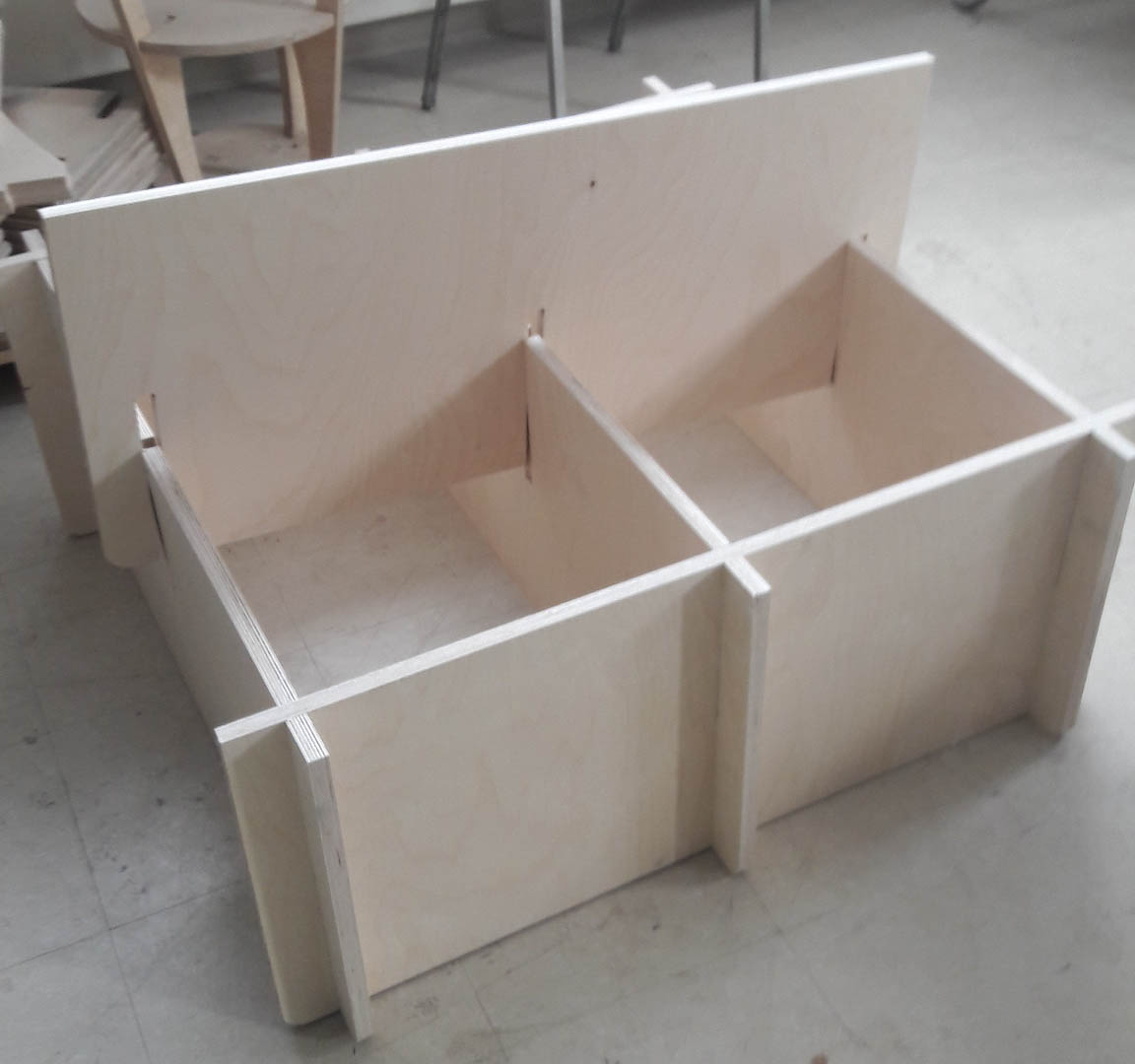
First, for this project I decided to make bookshelf that is easy to transport for this reason I wanted to integrate press fit joints in the design so i can to assemble, de-assemble the wood parts easily.
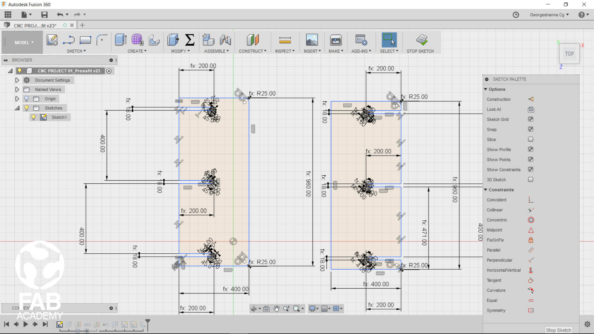
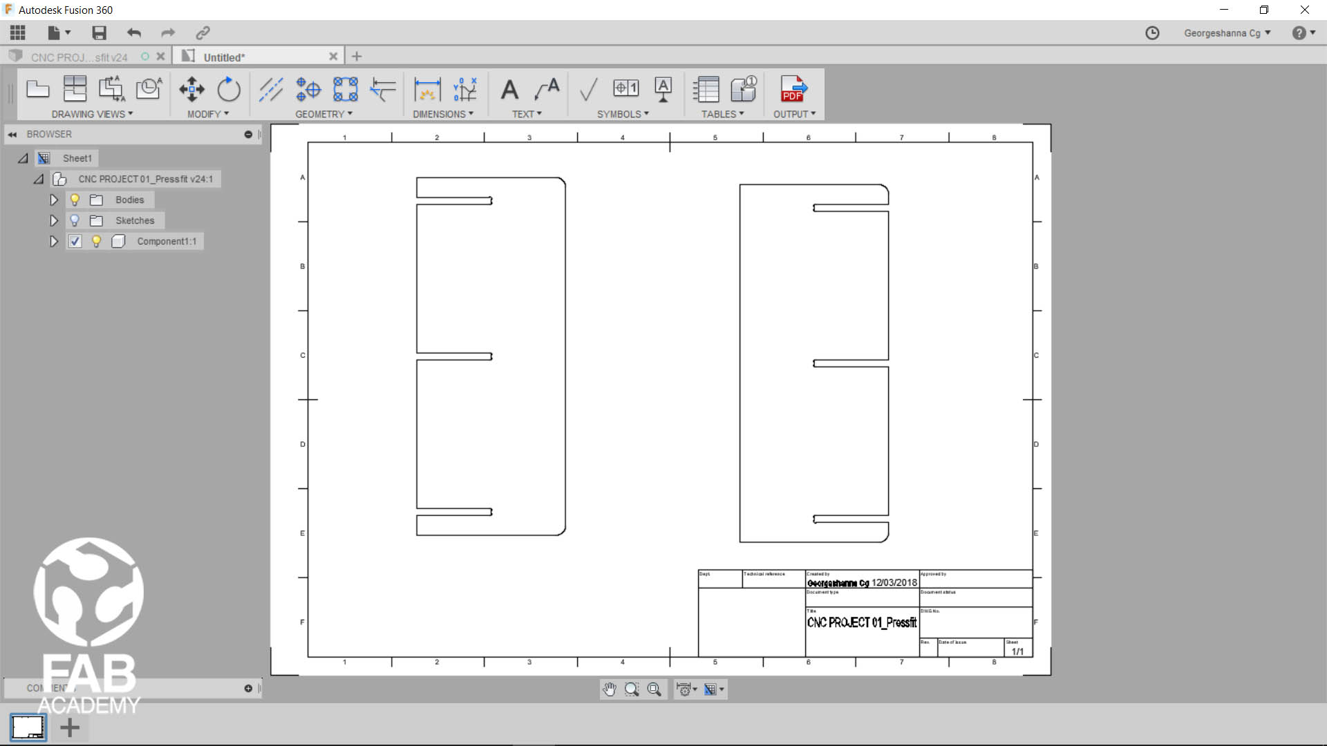
To begin with first I started with drawing all the parts in fusion for this job I had to fabricate mainly 6 parts and then I applied sketch constraints and dimensions along with the dog bone joints .
as you see in image # 1 , 2 the the design is fully parametric this allows me to modify the dimensions whenever I want later on.
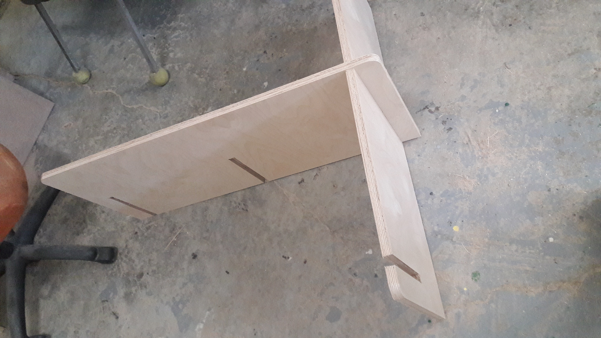
Adding the dog bones joints was an easy task I had decided to do this manually not by using any 3thd party plug-in since I have 2 parts only , To learn how to add dog-bon I just followed youtube tutorial the link for the tutorial is listed in the useful tips and links section.
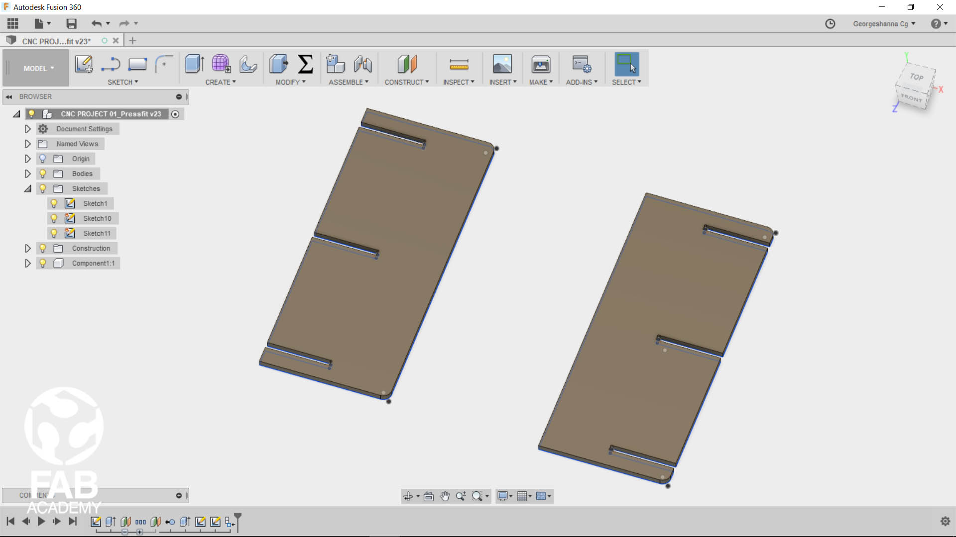
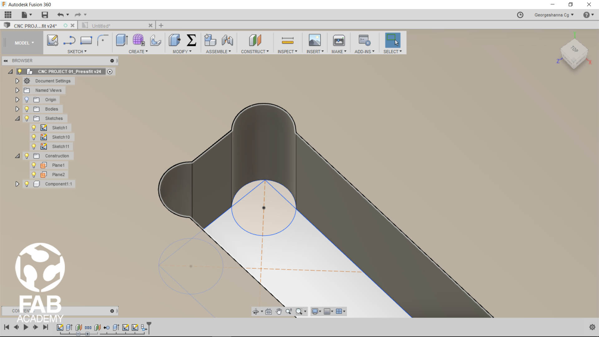
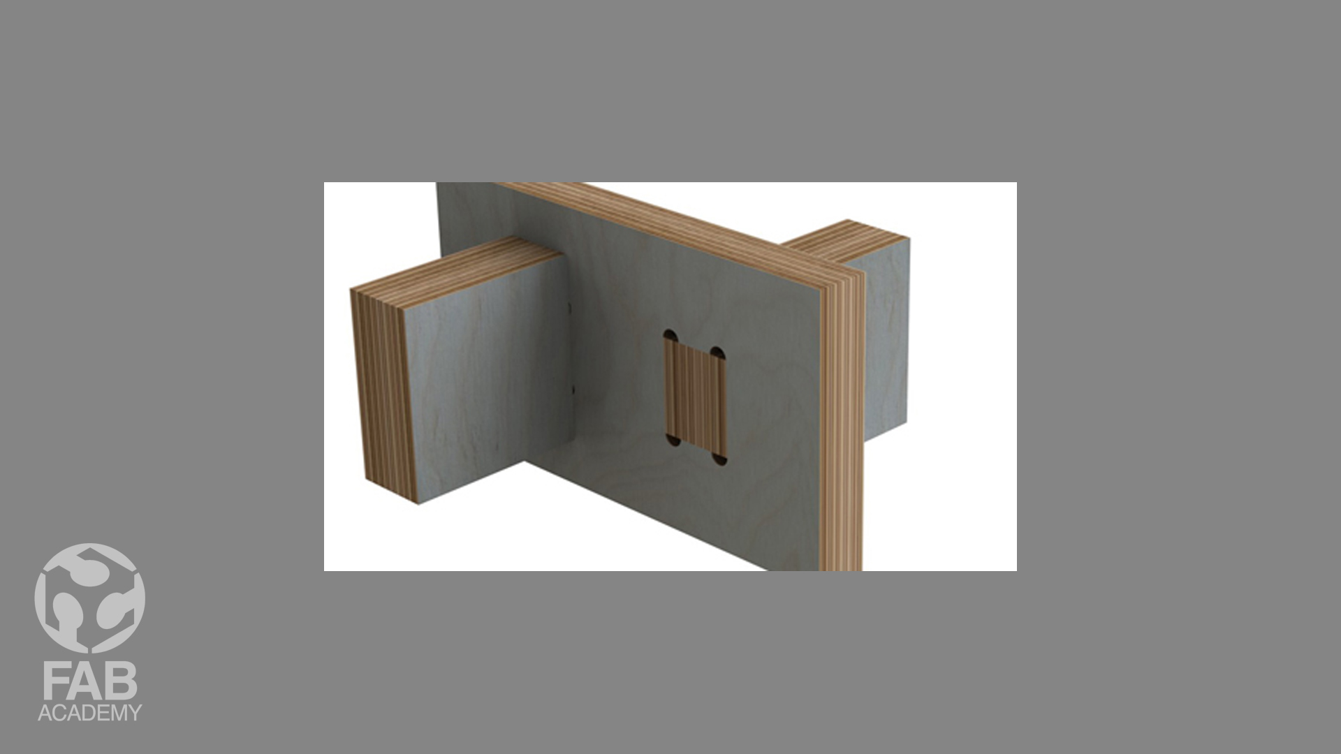
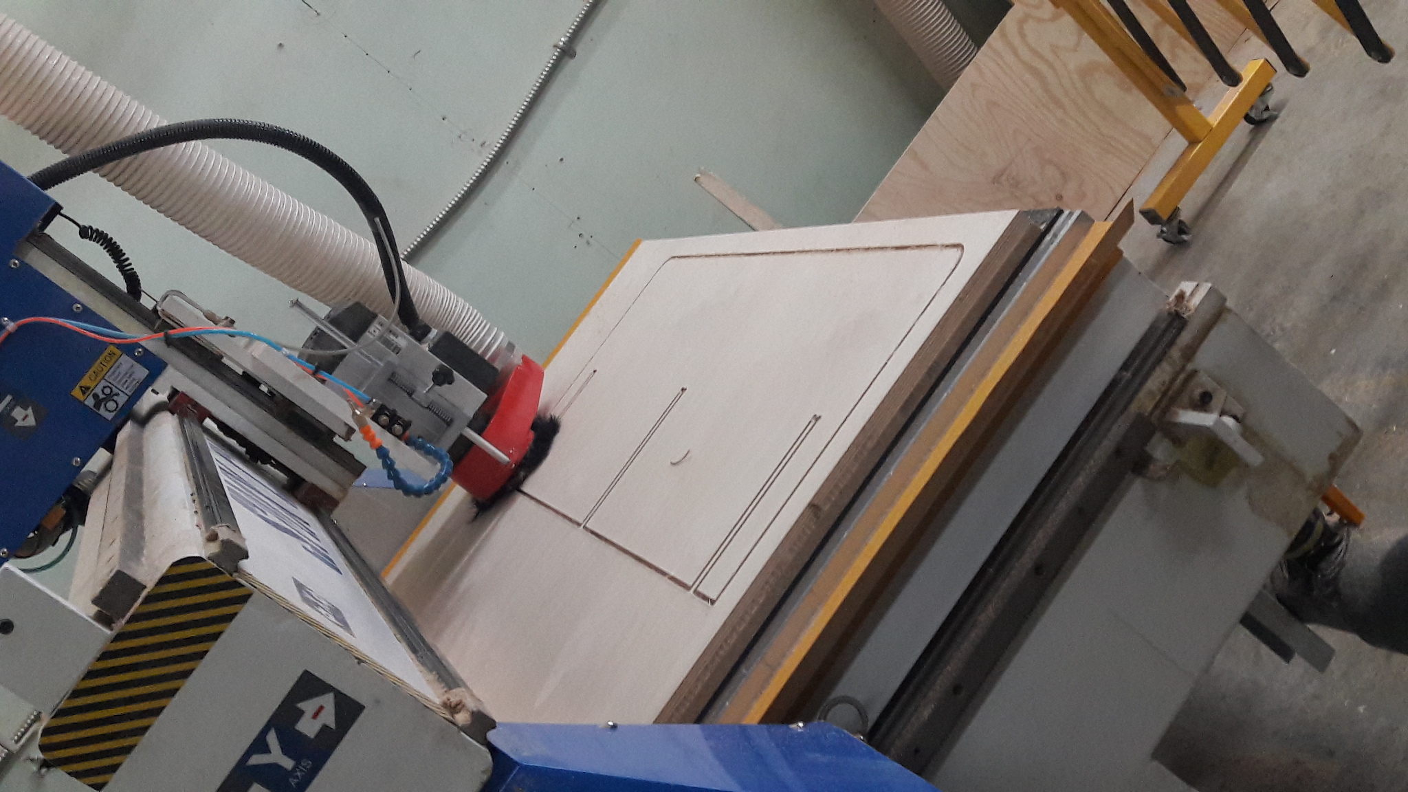
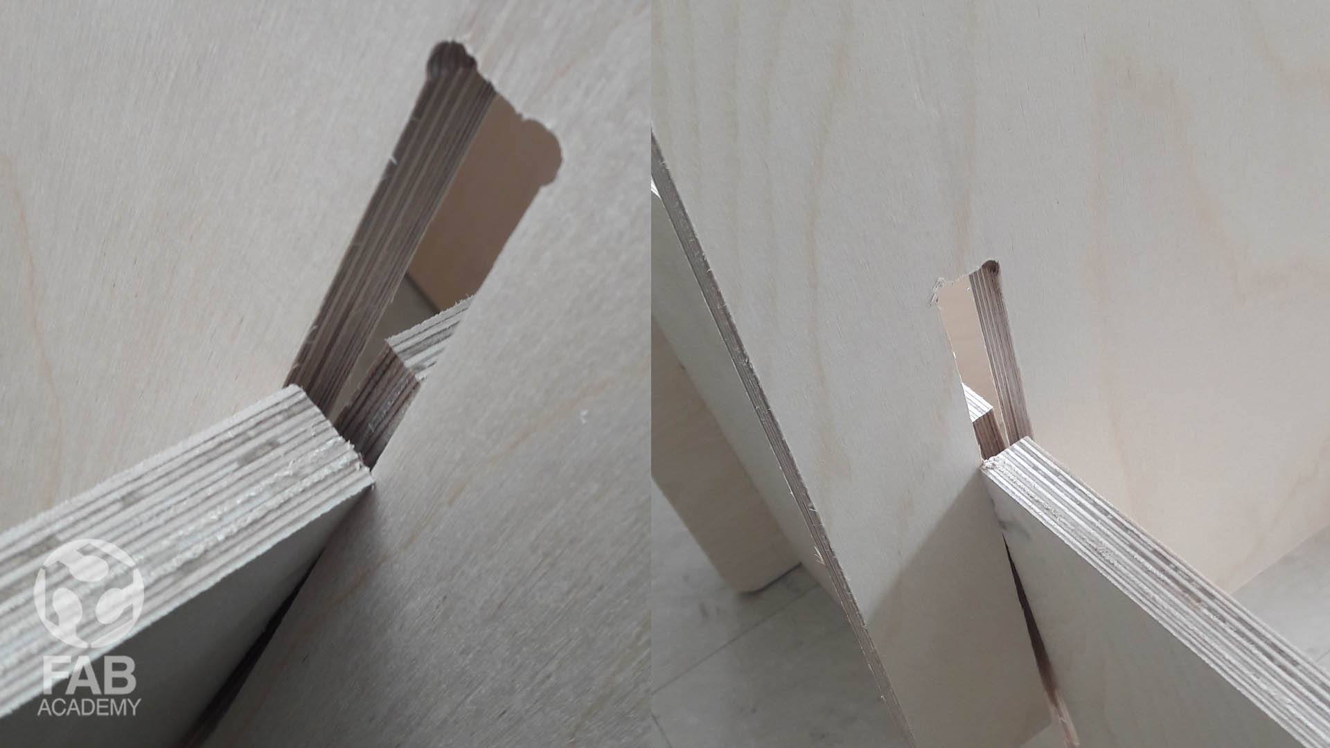
Adding dog bone joints is a vital thing because they allow you slot material together as shown in image #5.
GENERATING THE TOOLPATH
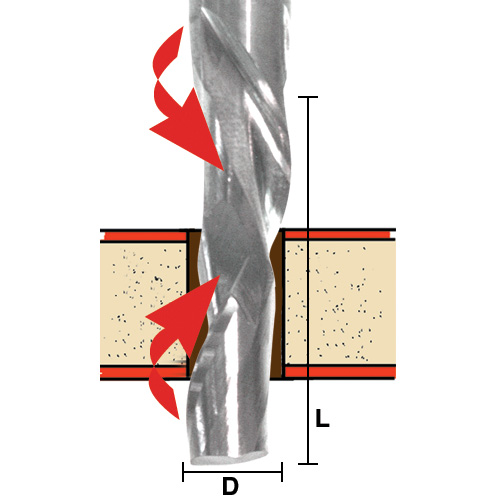
The second step in the process was importing the pdf file that was generated in fusion 360 into winpcsign cnc software in order to generate the G-code file, So for preparing the necessary G-code file for cutting the plywood board we decided to used 1/4 compression bit Compression bits are very useful for cutting plywood because they combine the benefits of both upcut and down-cut end mills, ensuring a smooth top and bottom face when cutting laminates and plywood at full depth passes and they considerably reducing cut time. Images #11 shows how compression bit works.
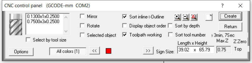
After that we had to use the below settings that were saved as a pre-settings profile in WINPCSIGN software by our 2nd instructor francois
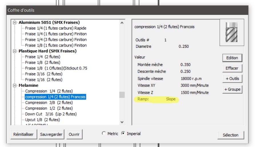
The feed rate and the spindle speed rates we used are listed below and they are also shown in image #08
feed rate (x,y) - 3000 mm/minute
plunge rate (z) - 1500 mm/minute
18000 r.p.m.
slope style ramp
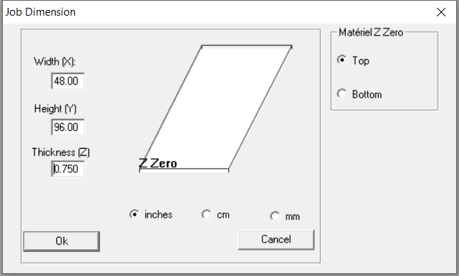
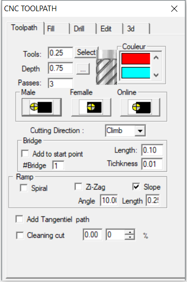
Then from the cnc toolpath menu we had to specify the tool we had to use in our case we set it to 0.25” along with the depth of each pass the depth of each pass means the travel distance in Z direction per pass while milling the material and also we had to specify how many passes we want to use until the milling bit reaches the bottom of the material.
Below are the cnc toolpath settings we used and they are also shown in image #09
tool - 0.25"
depth - 0.75"
number of passes – 3
And I since I had to cut outer paths only and because did not have any inside cuts I chose (male) option as shown in image #09 this way the milling bit will move along the outside edge of the path .
As for the slop we used slope ramp since Francois
mentioned that slop ramp is used when we want to slide down in the wooden board on a certain angle and this can put less pressure on the milling bit and it can lower the risk of breaking it while milling.
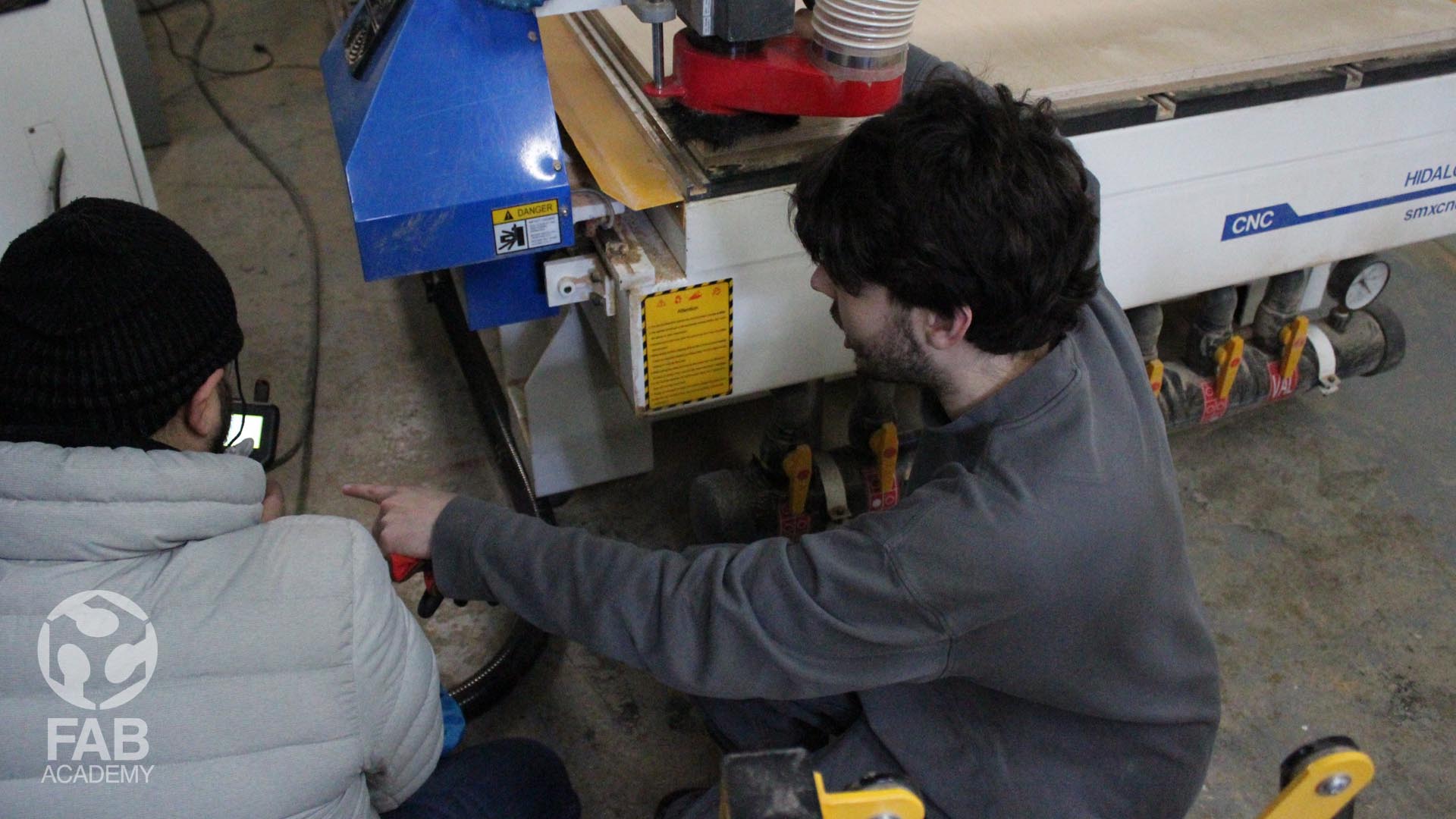
However Since our big cnc machine is placed in another location far away from the downtown area where échoFab is located it was not accessible by any of us us on a daily basis.
so in order to speed up the process that day and since we were four students and we all had to finalize our projects in the same day we could not prepare any test joints because we had to work super-fast with our instructor Francois
who prepared for us the pre-setting for the machine.
Initially we were told that the thickness of the Russian birch plywood is 0.75” so our parametric designs in fusion were adjusted accordingly to that dimensions however it was me who started first using the machine since my design files were ready to go so once me and Francois
placed the big wood panel on the cnc vacuum table and after starting milling the first part of my design we stopped the machine to check if the kerf thickness is working fine when joining it with another piece that has the same thickness before proceeding with cutting the rest of the elements.
However, surprisingly we discovered that we made a big mistake, because the wood panel has metric dimensions and the thickness was 18mm instead of 0,75 inch so based on that I informed my 3 other friends Alec , Marc and Geoffroi in order to re-adjust their designs accordingly.
Based on that I re-adjusted the thickness of my wood in fusion and instead of 19.05 mm I used 17.09 mm and this worked fine with me later on when I assembled all the parts togather.
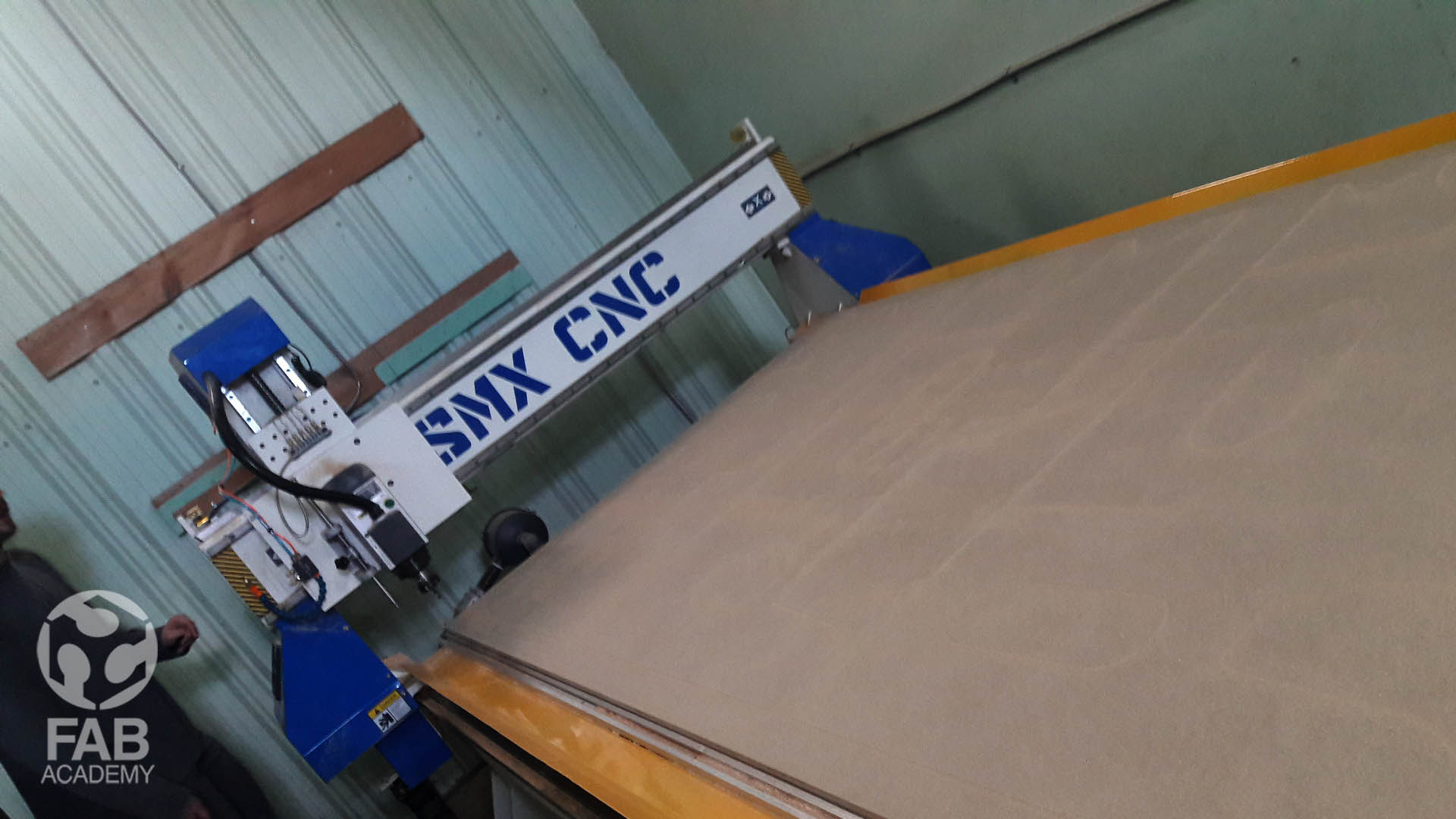
USING THE CNC
The cnc we used was a real monster comparing to the small CNC we use usually for milling our PCB boards the cutting zone X, Y, Z (mm) is 1550 x 3050 x 200 mm (61’’ x 120’’ x 7.75’’)
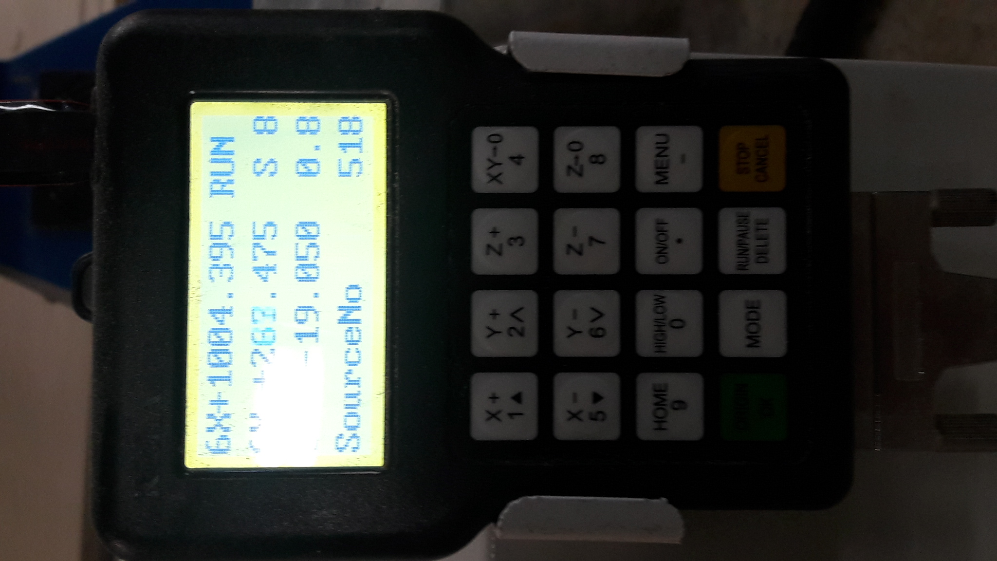
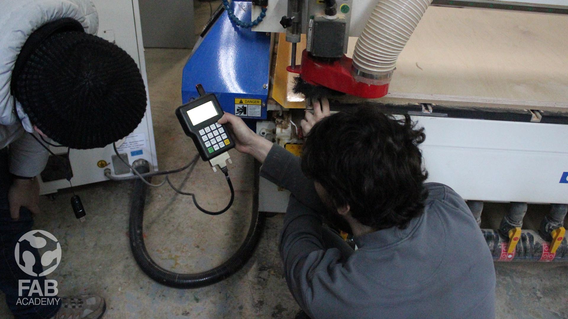
To use the machine first we opened the G-code file and we plugged the flash memory card into the DSP handle which were using to control the machine.
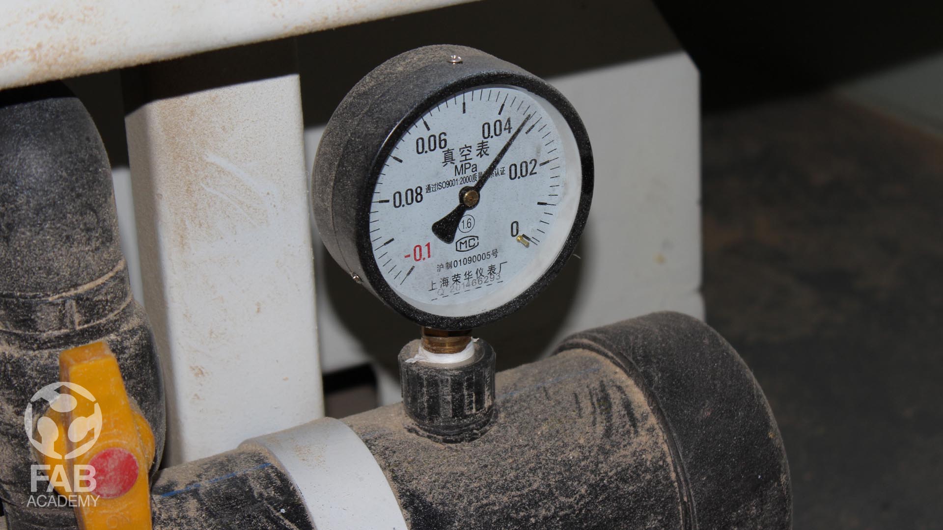
And then we had to place the materials on top of the vacuum table and then we opened the vacuum bed valves in oder to pull the wooden board down to fix them firmly on the vacuum table in oder to prevent the board from moving while the machine is milling.
I learned that activating the vacuum table before zeroing out the machine is a very important step because it helps alto in achieving accuracy and precision while cutting and engraving
since it removes all the air from underneath the wooden sheet and it also remove any existing warp in the wood.
and then we had to zero it out as shown in image #20 by using the DSP handle controller and by using a touch plate that comes with the machine .
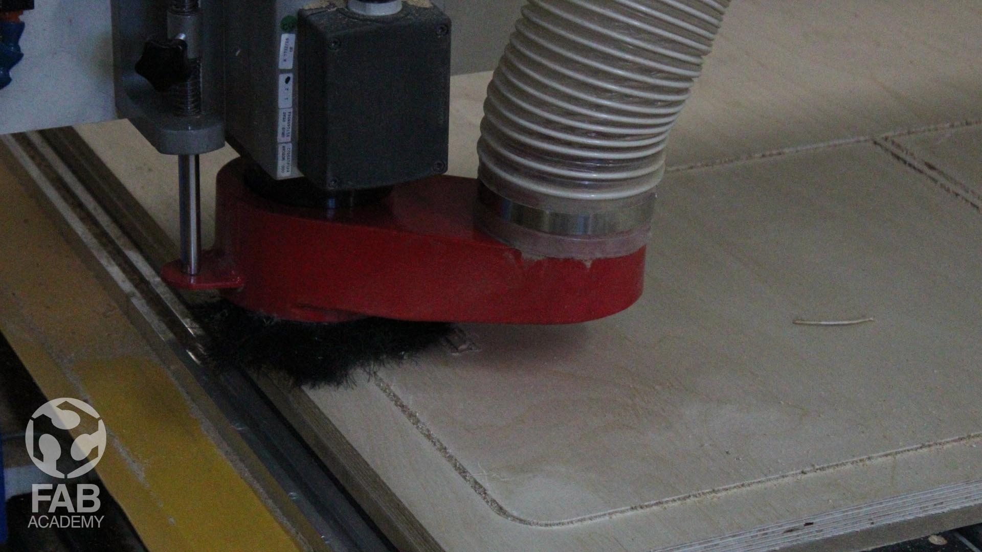
After the machine was zeroed out we turned on the dust COLLECTOR SYSTEM before activating the spindle and starting the machine.
Below is a list of the CNC technical specifications :
X, Y, Z Guide Linear guide, double on Z
Drive type Stepper motor
X, Y, Z CUTTING ZONE (MM) : 1550 x 3050 x 200 mm (61’’ x 120’’ x 7.75’’)
MAXIMUM SPEED : 25 000 mm/min (985’’/min)
SPINDLE : 4500W air cooling (6.0 HP)
INTERFACE : DSP handle (read USB memory directly )
REPEATABILITY : 0.025 mm (0.002 millième)
SPINDLE TOOLS : Φ 3.175(1/8’’), Φ 6 (1/4’’), Φ 12.7 (1/2’’)
POWER : AC220V ± 10% / 60Hz 1 phases (or 3 phases)
WEIGHT : 4400 lbs (2000kg)
SOFTWARE : WinPCSIGN CNC
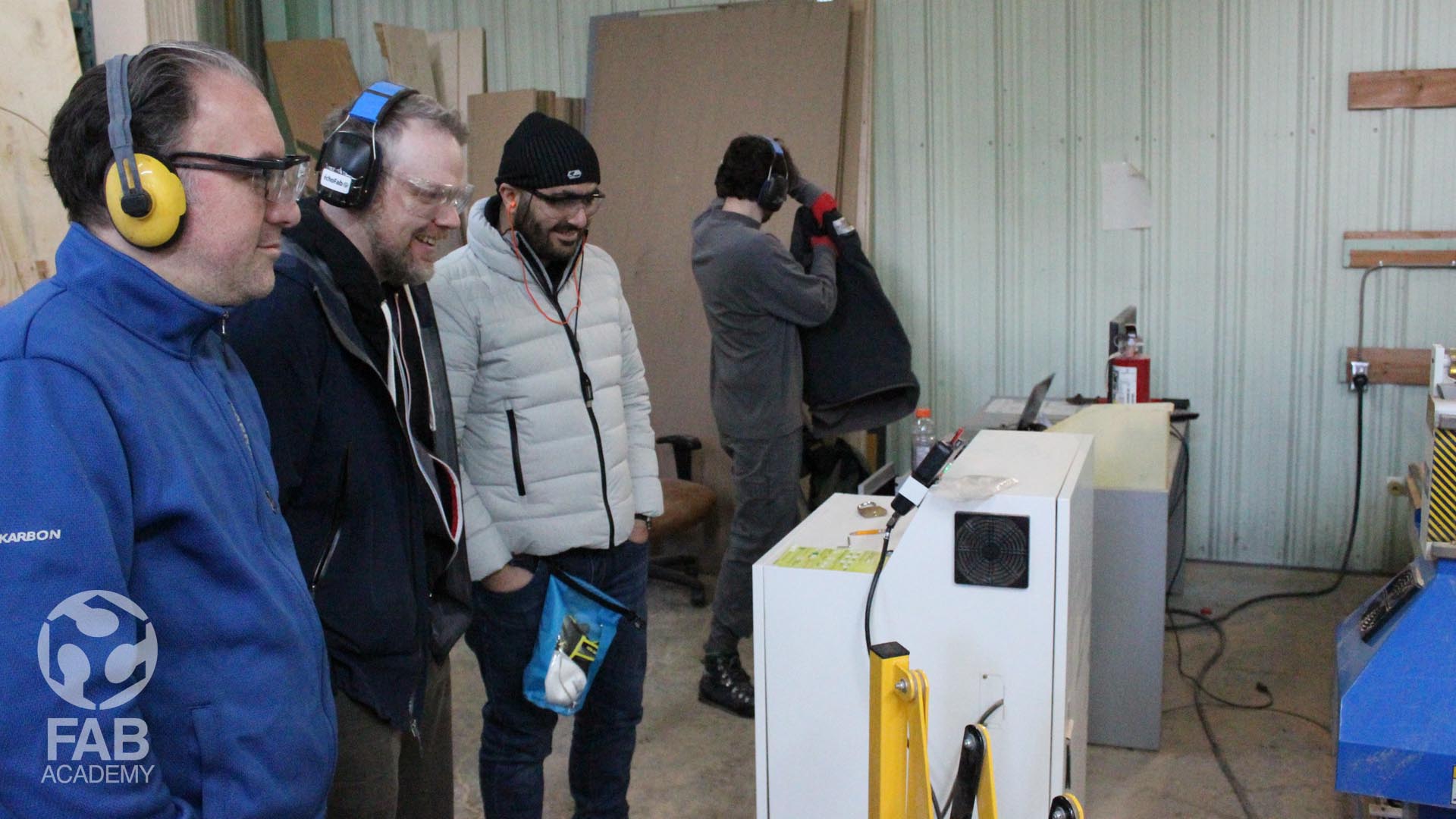
for using the machine safely and once the machine was on I had to stand behind the guard fence and I was wearing
personal safety equipments like safety glasses and hearing protection along with gloves as shown in images # 17 and # 22.
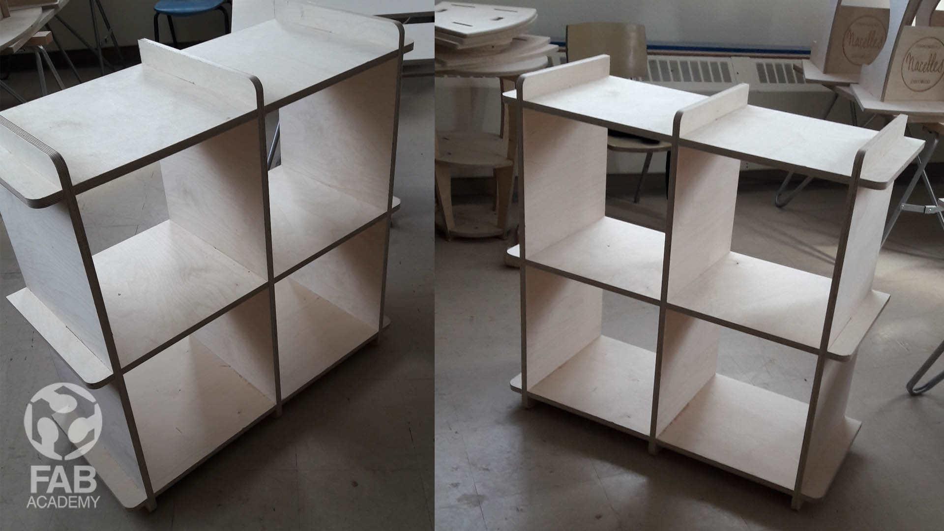
ASSEMBLING THE PARTS
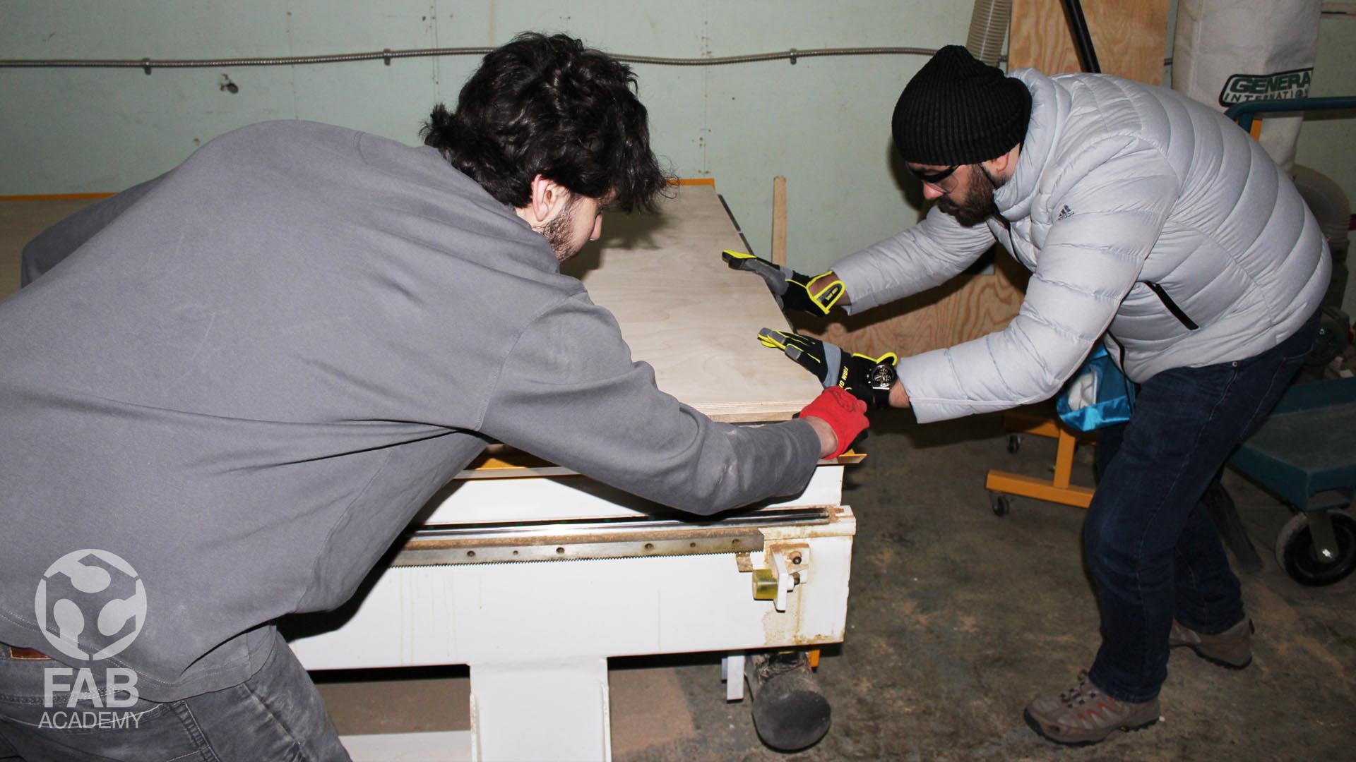
I was facing some difficulties when trying to assemble the wooden parts together the parts were squeezing and jamming together firmly from one side only it was hard for me even to pull them apart and assemble them correctly again . All of that happened because I was not pushing equally across the edge so in order to overcome that problem I used a wood mallet and a long piece of scrap wood in order to distribute the pressure equally across the wooden panel edge when knocking the pieces together following this method of assembling the pieces together worked perfectly for me finally.
USEFUL TIPS & LINKS
+ CNC ROUTING WITH FUSION 360 : HOW TO AVOID RADIUSED INSIDE CORNERS HERE.
+ SKETCHING & PARAMETRIC MODELING HERE.
+ FUSION 360 SKETCH CONSTRAINTS HERE.
NOTE: You cannot create drawings from only sketch elements or surface bodies.
DOWNLOAD SECTION
+ COMPUTER CONTROLLED MACHINING.f3d DOWNLOAD .
+ COMPUTER CONTROLLED MACHINING.pdf DOWNLOAD .
+ COMPUTER CONTROLLED MACHINING.svg DOWNLOAD .